Use this tool to evaluate CT Geometrical Calibration data.
Getting There
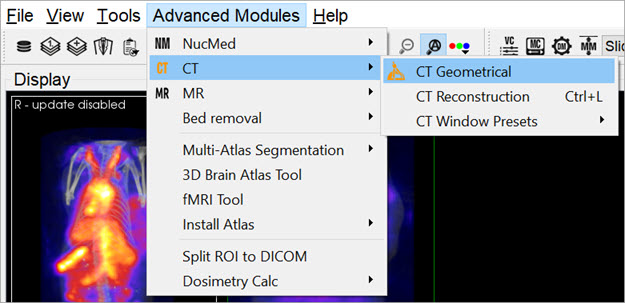
Access the CT Geometrical Calibration tool by going to Adanced Modules>CT>GT Geometrical.
Function
The gantry of the NanoSPECT has a reproducible wobble as it rotates around its axis. The CT Geometrical calibration measures this wobble and generates a file that is used to correct for the wobble in the reconstruction.
The calibration data is also used to assess the severity of the wobble and to insure that it does not exceed +/-0.5mm.
A CT Geometrical measurement consists of a set of projection data collected in a circular CT measurement of the Geometrical CT phantom. The orbits of the three metal balls embedded in the Plexiglas of the phantom are used to assess the wobble in the gantry. Example settings for this measurement include 55kVp, 360 projections, 1000ms. The protocol needed to run this measurement is called CT Geometrical and can be found in the Service Protocols section of the Nucline. After collecting the measurement data, it may be loaded into the CT Geometrical calibration panel using the Open button described below.
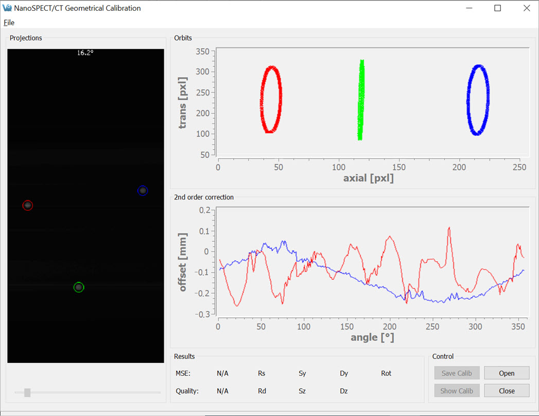
The CT Geometrical Calibration panel is divided into five sections: Projections, Orbits, 2nd Order Corrections, Results, and Control.
The Projections panel displays the projections collected in the calibration measurement as they are being analyzed. Each of the three metal fiducials is marked by a red, green, or blue circle. The progress of the measurement is also noted in this panel.
The Orbits panel displays the trajectory of the three metal fiducials as the projections are analyzed. The trajectories appear flat in the primary view; however, by drawing a box around a given trajectory it may be expanded to fill the entire panel, providing a more illustrative view.
To zoom in on a particular orbit, draw a box by holding down the left mouse button and dragging.
Upon release of the button, the display will show only the selected orbit. To return to the full view, just right-click.
The 2nd Order Corrections panel displays an important result of the calibration. This panel plots the axial and transaxial wobble of the gantry as it rotates. It is critical that these values be less than +/-0.5mm to enable successful correction of the gantry motion in the CT reconstruction.
The Results panel provides further calibration results, including a mean-square error (MSE) value that represents the deviation of the fiducials from their ideal trajectories. A one-word Quality assessment is provided as well as numerical values for other parameters including the radius of the source (Rs), radius of the detector (Rd), offsets of the source axially (Sz) and transaxially (Sy), and offsets of the detector axially (Dz) and transaxially (Dy).
The Control panel houses four buttons, including:
| Button | Function |
|---|---|
| Open | Opens the Data Browser where a CT Geometrical dataset may be selected for analysis. |
| Close | Closes the CT Geometrical panel. |
| Save Calib | Saves the existing calibration in the format used by the NanoSPECT/CT. |
| Show Calib | Shows the existing calibration in the format used by the NanoSPECT/CT. |